Sunday, July 31, 2016

Final Stages of Alberg 30 Mast Beam Reinforcement


Guys, here is a much needed update to the blog. 
I have finally got the mast support reinforcement 90% complete. I have all the major pieces made and in place. Now all that's left is the finish work. That will come later this fall when working inside the boat is more feasible...right now it is just too hot.

I first drew the archway on the G10 which would become the basis for the support. It took several attempts to get the archway the way I wanted it. 

If you look closely you can see that I epoxied another piece of G10 that spanned between the doorway. This provided additional surface area for the main beam to rest on. Total thickness is 3/4 of an inch.

After obtaining the arch I wanted, I took piece over to my friend's machine shop to use his large bandsaw. It makes quick work of of the G10!

You can see just how large this bandsaw is as I began to fabricate the knees for the addition beam.

All rough cut, the blade on the bandsaw is an inch thick so it does not make very tight radii.

After some time with a small pneumatic angle grinder and some 36 grit the knees were all shaped and ready for drilling


The archway bolted in place with new 304 stainless hardware.

And there is my idea of a proper mast support beam for a liner Alberg 30

You can see that it is all bolted together, even the knees are thru-bolted. I will not be stopping there though. I will be epoxying the whole thing together with heavy radius-ed fillets.  

This is the view from the v-berth. I added some G10 plate to the bulkhead where the fasteners passed through. I wanted to spread any load out over a larger area.

Another v-berth angle.

As stated earlier all the rough work is completed on the new main support beam and reinforcement. I still have all the finish work to do. That will include rounding and sanding all the sharp edges of the knees and archway. I can then clean and epoxy it all together.

Most of these photos were taken at the end of May, and since then I have moved onto the stbd side decks for recore and repair. The weather these past few weeks has not been conductive to any outside work. The outside air temperature has been just below or just over 100 degrees with heat index most days topping 110. Not fun for a redhead, we gingers just cannot cope with that type of heat.
Stay tuned as I update you on starboard side deck jobs.

Sunday, May 8, 2016

Alberg 30 Refit: Alberg 30 Mast Beam Reinforcement Coming Together

 Spring time is finally here. The weather has been consistently about 50 degrees at night, 60-65 during the day, just perfect for epoxy work. I've also had a week off from running the ferry, giving me a great opportunity to get some much needed boat work completed. This beam project is starting to come together. If you were confused about what I was trying to accomplish maybe this series of pictures will help. 
I have been using some higher level mathematics to construct this new reinforcement and I don't want to bore anyone with the details so I'll just say.....I hope it works. A lot of time and backyard engineering has gone into this project. 

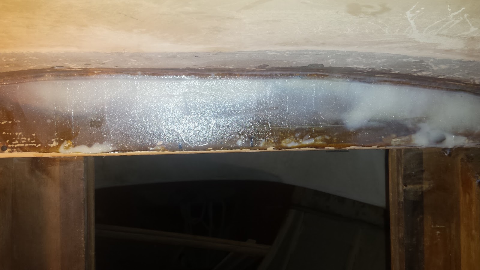
 This is the mast beam all stripped down and waiting for reinforcement.
(This was a photo from last post)

Here I've added some WestSystem 406 thickened epoxy to help bring the surface of the original beam level. What you cannot see is the several layers of 1708 biaxial fiberglass cloth I added to increase the strength of the support. As the original epoxy from applying the cloth began to gel, I added the thickened epoxy and then let it set overnight.

After sanding the beam smooth it was time to drill the holes through the original beam and new G10 reinforcement plate. For all those who wonder what is in the original beam of the "liner" Albergs, there is in fact aluminum in there, although I believe it's just two separate 1/4" plates. When drilling into the aluminum on the first hole, as expected I hit the aluminum but then rather quickly I was through it. As the drill bit continued I hit another piece of aluminum. I was able to drill through that rather quickly as well and before I knew it the drill bit was through the other side. The hole on the starboard side drilled identically, so for all those that are curious my boat has what appear to be two separate pieces of 1/4" aluminum within the beam.

The new G10 reinforcement all epoxied in....now on to the new beam that will reinforce the aft part of the mast step. I asked the first mate to coat all the new stainless hardware with a balm so the epoxy wouldn't stick to it. I intend to leave them in when it's all finished but for now I want them removable so I could sand everything down without them getting in the way.

Out came the trusty orbital, armed with 36 grit disc. Sanding commenced on all 12 pieces that make up the new 1" X 3" beam

Getting each piece sanded was not too bad. After this step all pieces were wiped thoroughly with acetone.

Here is the new beam in place. I use thickened epoxy to laminate the new beam. My plan all along was to laminate it in its final resting place. I drilled 3 small 1/4" holes and passed bolts through to the coach roof top. These bolts were fastened tight by the first mate out on deck. They hold the center of the beam firmly in place. Next step was to apply pressure to the outer edges of the beam. I accomplished that with 2 scissor jacks and some 1"x 1" pieces of lumber. I then jacked some pressure into the new beam.
WHAT A MESS!! All the excess epoxy started oozing everywhere. Luckily I was able to control it. I left this setup and allowed it to harden for two days just to be certain. West Systems says complete curing is 1-4 days.

Next I removed all the hardware and jacks. I broke out the orbital and went to town. Everything cleaned up nicely. I am still in the building process so it doesn't have to look perfect just yet.

Next I cut a new lower piece, you can see it sandwiched in between the piece that will eventually make the archway and the newly-placed reinforcement. I made the piece wide enough to sit under both sides of the beam reinforcement. This will also provide a solid surface for the archway to butt up against. 

Then it was time to start making templates for the knees (gussets) that will support the newly laminated beam.

Straight on shot of my reinforcement project

I now have templates for the port and starboard knee. I also did a center knee that is not pictured.

Starboard knee

This template was for the forward mast beam reinforcement plate. Once I had this cut and drilled, it was time to start cleaning everything up with the orbital, give everything an acetone bath and epoxy it into place.

I now have everything epoxied in place and will leave it to cure for a few days.

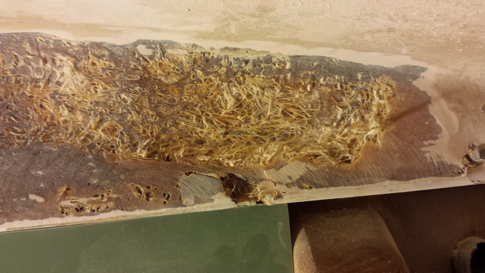
 G10 reinforcement plate viewed from the v-berth. I gave the original beam forward side the same treatment as the aft side. I ground away all the loose and poorly laid up material. I filled it with fiberglass cloth and thickened epoxy. Only difference is I did it all in one day. I am not familiar enough with the West Systems epoxy and how long I have to work with it before it starts to cure that with proper planning and everything laid out I can get much more accomplished rather than having to go through several curing cycles. Speeds things up quite a bit.

I accomplished a ton of stuff this weekend. I will take those templates I made for the knees and fabricate them from 3/4" G10. Once the knees are fabricated I will make the archway. 
We'll see how it goes!


Sunday, March 27, 2016

Alberg 30 Refit: Mast Support Beam & An Unexpected Tent Shelter Repair

Happy Easter to all!
I've been delinquent in posting perhaps, but there has been plenty of work going on. The weather has been a factor lately too. February/March are typically the worst months for weather and that held true this year. Although it has been unusually warmer, the mild days have been sporadic and not really consistent enough to start any epoxy or fiberglass work.
We had a severe line of thunderstorms that came through toward the end of February and caused quite a bit of damage to my boat shelter. I feel fortunate that this is all that happened because no more than 30 miles to the west several people were killed by tornadoes from those same storms.

After assembling the tent I knew that it would have to be secured by straps or it would be blown away. I intentionally did not design it as a permanent structure so I could avoid problems with the city code inspector. For over a year and through several storms it has worked quite well...until recently. This failed strap is what I believe caused my tent damage. At its worst, the storm winds kicked up to near-hurricane speeds for for a brief 10-15 min window. It was during this period that the strap broke.

This picture was taken the next day, after I had already moved the tent off the house. During the storm, once the strap broke the tent became airborne...or at least tried to. In an effort to move to the next town over, the tent bent and twisted the front half of the structure supports and buttressed up against the side of the house. It caused some minor damage to my gutters which was not too big a deal. The damage was minimal and could be repaired.  I will note that even with the failed strap, our Sal was kept dry for the most part. It took me a few days to get the bent pieces replaced and I am happy to report the tent is back up and stronger than before.

The boat refit is coming along slowly. I have been gathering pieces and making a plan but execution of said plan has been a bit lacking. Work and side projects have been taking up a ton of time as I have been running the ferry both days of every weekend to generate money for more boat parts. A valid excuse when one is refitting a boat on a budget. As the weather warms up I will have both the funds and the time to pick up speed...at least that's the plan.
Lately I've been working on the deck beam and now have it ready to go back together.

Here is the deck beam on my "Liner" Alberg 30 all sanded and awaiting additional support. 

I will lay new layers of 1708 biaxial cloth in these low spots before bolting in beam reinforcement.

Looking to the port side of the beam; not as many low spots but still a few.

Here is the new plate that will be the back bone of the reinforcement and repair.

I am using this router table to help shape the piece of 3/8 G10 board.

A nice 1/4 rounded edge, this stuff works just like wood.

New piece clamped into place for a test fit.


After plate is mounted I will add a 3" wide beam aft of it. This beam will support the aft part of the mast step.

The beam will be made of 8 pieces of 1/8" thick G10 laminated together to form the new beam. That gap seen is caused by the deflection in the cabin top from original damage. I was advised to leave the deflection and just build the new support off of it. The gap will be filled with 406 thickened epoxy.

Same gap to port

Once all of it is epoxied in place I will make gussets from the face of the original beam to the new bottom of the laminated beam.

If you are unclear about the repair stay tuned, I hope to have it done in the next few weeks and I will post pics of process and product as it comes together. Once the repairs belowdecks are complete I will begin the topsides of the mast step. Once I get  the mast step back together I will pick up on deck re-coring. Much work to do but looking forward to it.

Thank you for following!

Wednesday, January 27, 2016

Alberg 30 Refit: Digging into the Mast Support Beam

Over the last few days I've been digging into the mast beam, carefully. I have not been too happy with what I have been uncovering. I am going at this slowly because I just don't know what is under the liner, and I don't want to cause any further damage by being careless. 
Below are photos of what I have found so far. 

I used a large flat blade screwdriver and began digging into the loose layup. I was able to dig all of the loose area out in just a few minutes....it's no wonder the liner on my Alberg cracked and folded in on itself....it was paper thin and wasn't made very well at all.

The port or left side of the liner appears to be in better shape but it still isn't anything to brag about. The marks you see are measurement points. I am making a brace that will be epoxied and bolted through the main beam to add strength to the beam structure (more about that in a future post).

After taking a pneumatic disc sander to the area I uncovered many voids and poor layup areas. The G10 board below the main beam is part of my plan to add structural integrity to the existing beam. I am working on a blog post to explain, in detail, my plans for the mast beam reinforcement; but for now just to summarize it: I am going to add an archway that ties the two bulkheads together to help distribute the pressure of the main beam.

More loose and poorly laid up fiberglass on the port side but luckily it didn't extend out nearly as far as the starboard side.  

Another huge void and poor layup on starboard side.

A close up of the void. I will fill this area with thickened epoxy.

I intend to grind out all that loose stuff from the beam area. Once it's cleaned up I will add a few layers of biaxial fiberglass cloth, making a nice smooth surface to begin the repair work.


A short video showing what I discovered in the main beam area and a peek into my Master Plan to add reinforcement to the mast support beam.

Making progress!


Monday, January 25, 2016

Alberg 30 Refit: Mast Step Repair

As mentioned in a recent post my Alberg 30 suffers from mast support compression. This is one major area on which I need to focus. 
I have begun some investigative work to determine the extent of the damage, starting with poking and drilling into the beam area. I was not too happy with some of the results. However, nothing so far seems to be irreparable.

I started by cutting a few lines into the damaged area. I used the oscillating tool for this.

As I was poking into the damaged area I found some very poorly laid up fiberglass. I did not chase this area all the way to its end, but I think it goes at least another 3 or 4 inches toward the starboard bulkhead.

Good news is that this poor fiberglass lay up appears to be only skin deep...literally. My 1971 Alberg 30 is what is known as a "liner" boat...meaning Whitby Boat works created a sort of "beauty" layer (similar to the headliner in a car) to enhance the appearance inside the boat and give it a more finished look. Without this liner you would see the bare fiberglass, which was probably a lot of work for them to clean and make presentable, so the liner simplified the finishing process. The damage so far appears to be a poor lay up of just the liner. 
Next, I drilled a few exploratory holes into the beam itself and I found the aluminum beam that is encased in the fiberglass. That is also good news. I suspected with all the compression that maybe the aluminum beam was a unicorn of sorts. Well, it's no myth; I located it. 

So why did the mast compress the deck? My answer is purely speculation but I believe quite plausible.  I have described my theory in the sequence of photos below:

In this photo you can see the mast step area (the actual mast step is a rectangle pad with 6 holes in it). Those holes are drilled into the deck. Over the years of hard use and poor maintenance, water seeped past those holes and into the balsa core below the mast step. Yes, there is balsa core below the mast step. I believe this was the major cause of the compression. Water got into the core, turned it into rotten mush and most of the integrity was lost.

I set the mast step pieces back on the step itself for this picture. This photo shows what I consider to be a major design flaw. The blue lines drawn on the deck outline where the support beam is in relation to the mast step. You can see it is not centered.  This likely caused some of the excess compression to the rear of the mast support down below. This will be redesigned when put back together.

Another shot of how off center the mast step is compared to the support beam down below. 

With everything all marked I began to cut into the deck. To no one's surprise I found soaking wet rotten core.

Not pretty.

Much to my relief, the rotten core did not extend much further aft than the mast step.

Further destruction.

Ah yes, just what I always wanted to do...cut up my poor sailboat. Ugh.

Area all cut open and lower skin exposed.

A shot from down below looking out.

At the end of the day this is what I cut away. 

This is not the best photo but you can see the compression in the center of the mast step area.  I will build this area back up with solid fiberglass and my favorite G10 board.

I have begun to formulate a plan. My plan will include re-designing and strengthening the mast beam and mast step area from both above and below.
This is a 3-in wide strip of 1/8th inch G10. I will fabricate a laminated beam in this area to assist in the support of the step. 

More on the re-design and strengthening of the mast support to come!


Here is a video I shot the day I cut the mast step open. 

When will I finally be able to stop destroying the boat I so dearly love?